
[ad_1]
Components Required:
- DC Motor (12 V DC)
- Relay (12 V)
- Resistance
- Bell Push Button
- One-way Switch
- LED’s
- PCB
- Connecting Leads
- Terminal blocks
- Buzzer
Introduction
The sources of energy are various types in the globe but for vehicles the world still depended on crude oil in the form of Patrol and Diesel. We very well known that the petrol and diesel are limited sources for the use of long period of time therefore the importance of electrical power increases day by day and the world is trying to find solution in the form of electrical power.
Now a days the electrical vehicle demands are increasing continuously in the market but there are so many issues with the performance of electrical vehicles with different components of EV’s like short circuit of motor, heating of batteries, power losses, heating of operating coil etc.
In different information sources we continually find that EV’s are burning or the batteries heated up & blasting therefore in this project, we are going to discuss that how to protect motor and battery against short circuit by using relay in electrical vehicles as author prototype shown in fig.1 and the circuit diagram of prototypes is shown in fig.2
Many times accidentally terminals of batteries and other power supplies get short circuited. Due to this, they get hot and start degrading as well as produces arc also.
As we know that a short circuit current occurs when current travels along an unintended path, often where essentially no or a very low electrical impedance is encountered.
A short circuit protection is a protection against excessive current rating of equipment and it operates instantly. As soon as an over current is detected, the device trips and breaks the circuit.
Working and Testing
To operate this project, we have listed components above the working and designing of the circuit is very simple and easy to understand.
Initially in step 1 of operation the relay circuit is normally open and red LED glows when we connect a power source to the input terminal of the circuit.
In step 2 when we press bell push button, coil of the relay becomes active and it switches from normally closed to normally open contact. In this condition Green LED and motor are ON and starts to operate i.e. vehicle is starts to operate.
In step 3 here manually we short circuited the terminals of motor to understand the shot circuit condition in EV the voltage across the motor is lead to zero so relay becomes discharge because both relay and motor are connected in parallel as shown in prototype as well as in circuit diagram.
In step 4 hence if relay is discharged then Red LED and buzzer both are ON and thus motor and battery both are separated and protected.
Circuit Diagram
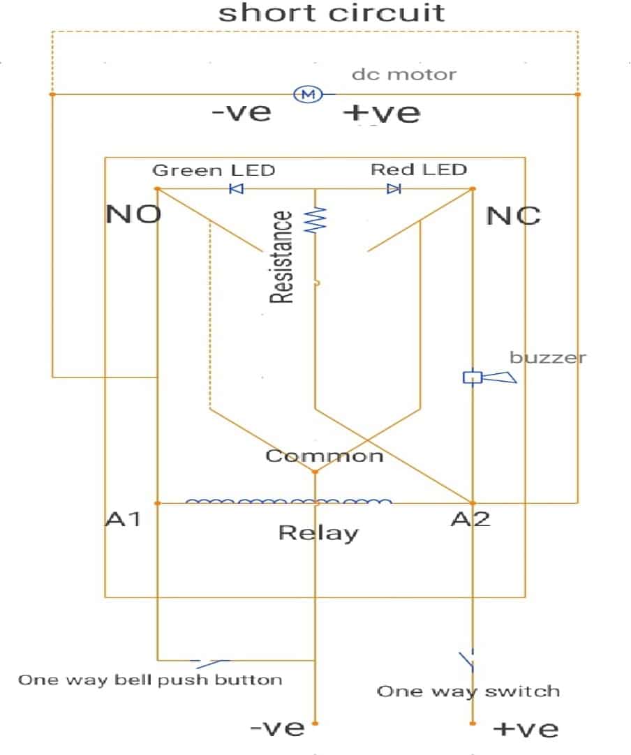
Conclusion:
The conclusion of this project is that we designed a prototype for resolving the problems of short circuit in electrical vehicles and we tested that we can save the motor after short circuit as well battery for discharging after short circuit therefore the life span of batteries increases and we know that the batteries and motor are the main part of EV and batteries are expensive therefore with this circuit we can protect motor and batteries of electrical vehicles.
[ad_2]
Source link


