
[ad_1]
Thermal cameras, or thermal accessories, are useful for thermal scanning-based fault detection, thermal throttle analysis, thermal monitoring, and many other purposes.
Thermal scanning is also used in monitoring the temperature of furnaces or boilers, or for analysing body temperature without physical contact-like detection of Covid-19 in a person.
While thermal cameras are expensive with their price anywhere between ₹30,000 and ₹100,000, and sometimes even higher, some cameras are available as external accessories for mobile phones. These can convert a phone into a thermal camera, but even these accessories can cost up to ₹30,000, or higher, which many of us may find still quite expensive for basic thermal analysis or thermal scanning or to test Covid-19 symptoms.
So, here is how you can make an affordable thermal camera accessory with which you can turn a phone into a thermal camera for as low as ₹5000 to ₹6000. This camera can be used to get a very basic thermal video and for other basic tasks like thermal screening, thermal testing analysis, and thermal monitoring.
| Bill of Material | ||
| Components | Quantity | Description |
| AMG 8833 (S1) | 1 | 8×8 Thermal Sensor |
| Raspberry Pi Zero W (MCU1) | 1 | For Processing Sensor Data |
| Micro USB to iPhone OTG (USB 1) | 1 | Male iPhone/USB type C to Male micro USB OTG |
| 3D Case | 1 | PLA/ABS 3D Printed Enclosure |
(EFY note. An on-the-go adaptor (OTG adaptor) can be used according to the phone on which this device is to be configured. For iPhone, we will need an iPhone OTG adaptor, and for an Android phone, a type-C USB.)
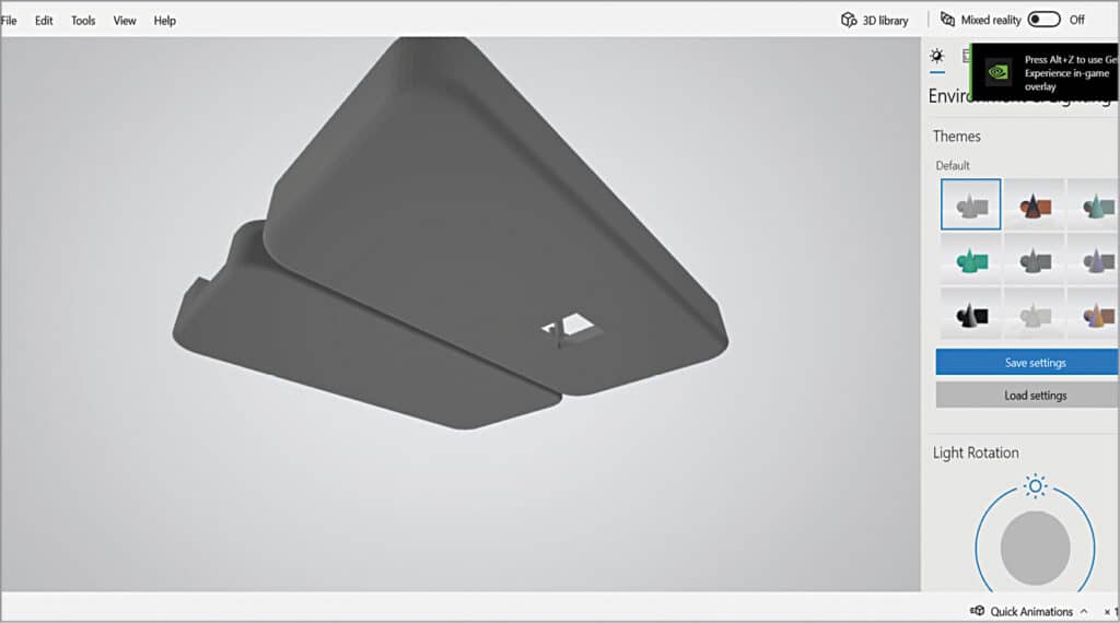
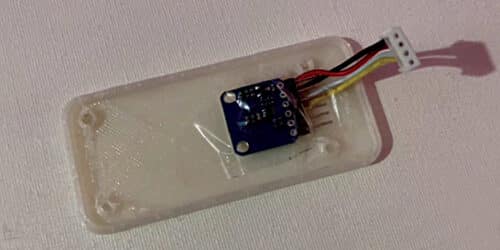
First, the body of the device needs to be designed in a way that supports and protects the components and the device. The thermal sensor and the Raspberry Pi Zero W are used here together. The enclosure/case of the device can be designed as per the size of the Raspberry Pi Zero W. A hole can be made at the bottom of the case to expose the thermal sensor. A cut for the USM micro OTG outlet can be provided at the top of the case, as shown in Fig. 3.
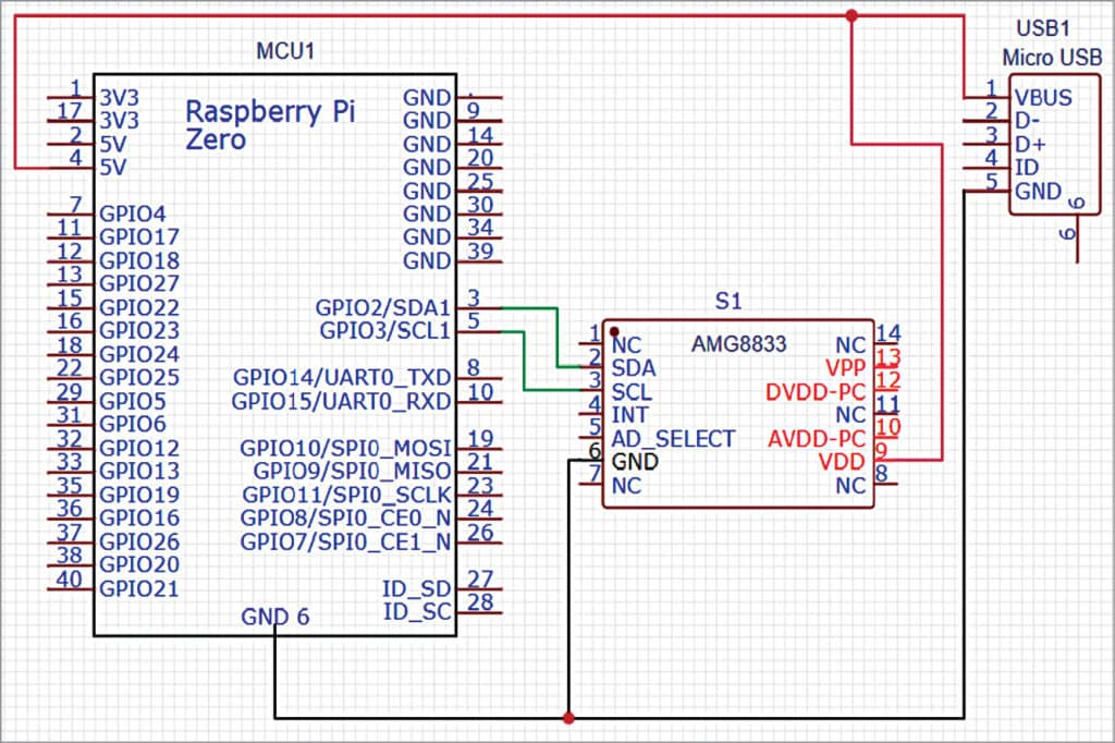
After designing the case, connect the sensor, Raspberry Pi and OTG as shown in the circuit diagram in Fig. 4. If you have an OTG with a micro USB male output, you can directly connect that micro USB to the Raspberry Pi micro USB input. Or else, you need to cut the wire of the OTG and solder the +ve wire to the 5V pin of the Raspberry Pi, and GND to the GND pin of the Raspberry Pi. For the iPhone, avoid using the soldering process and use the Micro USB male to iPhone male OTG connector.
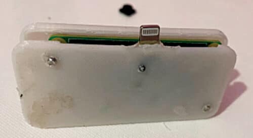
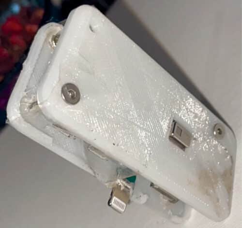
Do check all connections to avoid damaging your expensive phone. After connecting the OTG and sensor with the Raspberry Pi, fix the sensor, Raspberry Pi, and OTG adaptor inside the designed and 3D-printed enclosure (see Fig. 5, Fig. 6, and Fig. 7).

Coding
Install the Raspberry Pi with the latest Raspbian OS. Then enable I2C pepherial in Raspberry Pi, as the thermal sensor we are using is interfaced on I2C communication. Hence, to enable the I2C on Raspberry Pi, open terminal and run sudo raspi-config and then go to advance and interfacing option and enable the I2C and VNC.
Now, connect the Raspberry Pi to a phone’s hotspot or Wi-Fi network to which the phone is connected. Next, install a few libraries and modules that help us with interfacing the sensor and getting data from it, as well as viewing that data in video form. So open the Linux terminal and run the following command:
sudo pip3 install pygame
sudo pip3 install scipy
sudo pip3 install numpy
sudo pip3 install Adafruit_AMG88xx
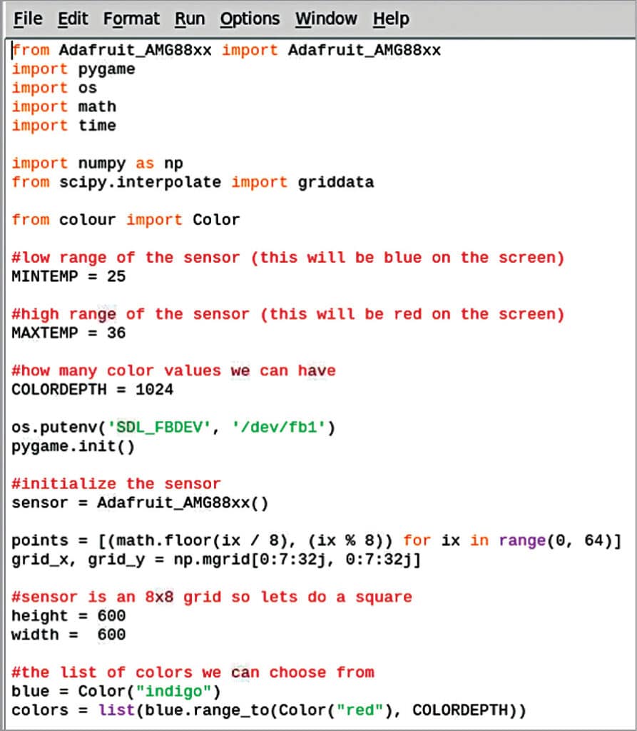
After installing the libraries, import all installed modules in the code. Then set the maximum and minimum temperature range to get the AMG sensor readings. Set the range between 22 and 45. Even a higher range can be set, depending on the requirement and the purpose for which you are using it. If it is to be used for thermal analysis and the temperature range is greater than 100, you can set the range accordingly.
Next, set the pygame window size, the size at which the video output for your thermal camera is obtained. Then map the sensor pixel data to red, green, blue, and yellow.
Let us understand how the thermal camera works. The thermal camera has a thermal sensor inside many small IR thermal sensors. Each thermal sensor acts as a pixel of the thermal camera and it is in the form of a matrix. So, if a good-quality, high-resolution thermal camera sensor is used, it has very small thermal sensors in the form of pixels.
Here, we are using the AMG8833 thermal sensor, so the pixel size is a matrix of 8×8. To get the real-time video, we map those pixels, that is, the small-sized IR thermal sensor data, with colours like blue, yellow, and red, where red depicts the hottest and blue the coldest. After colour mapping, the thermal image is formed that we see in any thermal camera video.
Fig. 8 shows the code setting the display size and sensor.
Testing
When the device is ready after preparing the above code, connect it to the charging port/USB of your iPhone or Android phone. Install the VNC viewer on the phone or PC on which you want to receive the thermal camera video.
If iPhone is being converted to a thermal camera by attaching it to this device, install the VNC viewer, available on the app store, on the iPhone. We need to insert the IP address and password of our Raspberry Pi and let the Pi connect to either a phone hotspot or to the same Wi-Fi network that our phone is connected to.
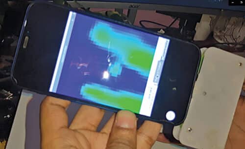
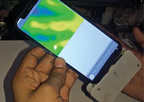
Now run the code that was prepared earlier to get the real-time thermal video. Move your hand near the thermal sensor device, or bring a hot object near the sensor device, and you can see the thermal video of the object .
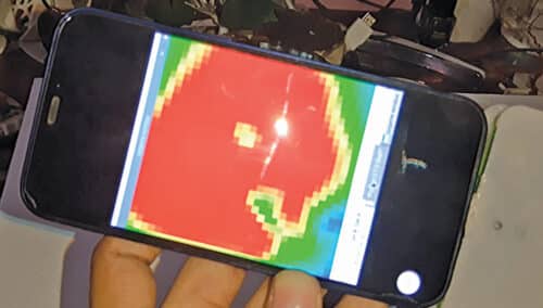
You have just designed the thermal screening attachment accessory for the phone. Fig. 9 and Fig. 10 show testing of the project.
Download source code
Ashwini Kumar Sinha is a technology enthusiast at EFY
[ad_2]
Source link


